
Gas Valve Troubleshooting and Safety: Furnaces, Dryers, Ovens, and Water Heaters
Terry Okafor
Master refrigeration tech and NATE-certified instructor who moonlights as the magazine's advice columnist. His 'Ask Big Terry' mailbag has been settling shop disputes and diagnosing mystery leaks since 2011.
Gas Valve Troubleshooting and Safety: Furnaces, Dryers, Ovens, and Water Heaters
Gas valve work sits at the intersection of electrical troubleshooting and gas safety — and both sides of that intersection carry real consequences if you get it wrong. The electrical testing is measurable and diagnostic. The safety side has no diagnostic gray areas: a leaking gas valve is a condemnable condition, full stop.
This guide covers how to test gas valves across all common residential gas appliances, when to repair versus replace, the safety protocols that apply to every gas call, and the NFPA and California regulatory context that determines your liability.
Safety Protocol: Before Any Gas Valve Work
The safety protocol is not optional and it does not shorten over time. Follow it on every call, including the repeat visit where you replaced that same valve six months ago.
Leak Detection Before and After
Before you start any gas valve diagnosis, perform a leak check on the gas supply connections at the appliance. Use a listed combustible gas detector (electronic), not soap bubbles alone. Soap bubbles won't detect small leaks in confined spaces, and they miss intermittent pressure-dependent leaks.
Acceptable instruments: combustible gas detector calibrated and bump-tested, or a liquid leak solution (soap or commercial product) as a secondary check on fittings you've accessed. Use both.
Leak check locations:
- The main supply shutoff valve (the quarter-turn ball valve on the supply line)
- Union fitting where the supply connects to the appliance gas line
- All flexible supply connectors
- The gas valve inlet and outlet fittings
- Any fittings you touched during the repair
After ANY work on gas connections, perform a full leak check before restoring power and attempting ignition. Document that you performed the check.
Shutoff Procedures
Appliance shutoff: The quarter-turn valve on the dedicated gas line to the appliance. Perpendicular to the pipe = closed. Parallel = open. If there is no accessible shutoff at the appliance, that is a code violation in California — the California Plumbing Code and CMC require an accessible shutoff within 6 feet of every gas appliance.
Main shutoff: At the gas meter on the exterior of the building. Requires a meter wrench (flat bar or crescent wrench, not a standard wrench — the meter valve body is designed for a specific tool). Do not use the meter shutoff unless you cannot access the appliance shutoff or you have a positive leak confirmed in the gas supply line.
When to use the main shutoff: Gas odor present throughout the structure, confirmed leak at the meter or main line, or the appliance shutoff is inaccessible, compromised, or appears to be leaking.
After using the main shutoff: Do not reopen it yourself unless you are trained and authorized to do so. The California DMO requirements and utility policies vary on who can restore service after a main shutoff. In most SoCal Gas and Southwest Gas territories, only a licensed contractor or the utility can reconnect service to verify all appliances are in a safe condition after a main shutoff.
Keep a documented record on every gas call: date, address, what was found, what was done, leak check performed and result. If a gas incident occurs at a property after you've worked on it, your documentation is your defense. A service report that says "gas valve replaced, leak check performed post-repair, no leaks detected" is the difference between a civil liability issue and a clear record. I've been deposed once in a gas-related incident. My documentation kept me out of it. The other tech involved had no records.
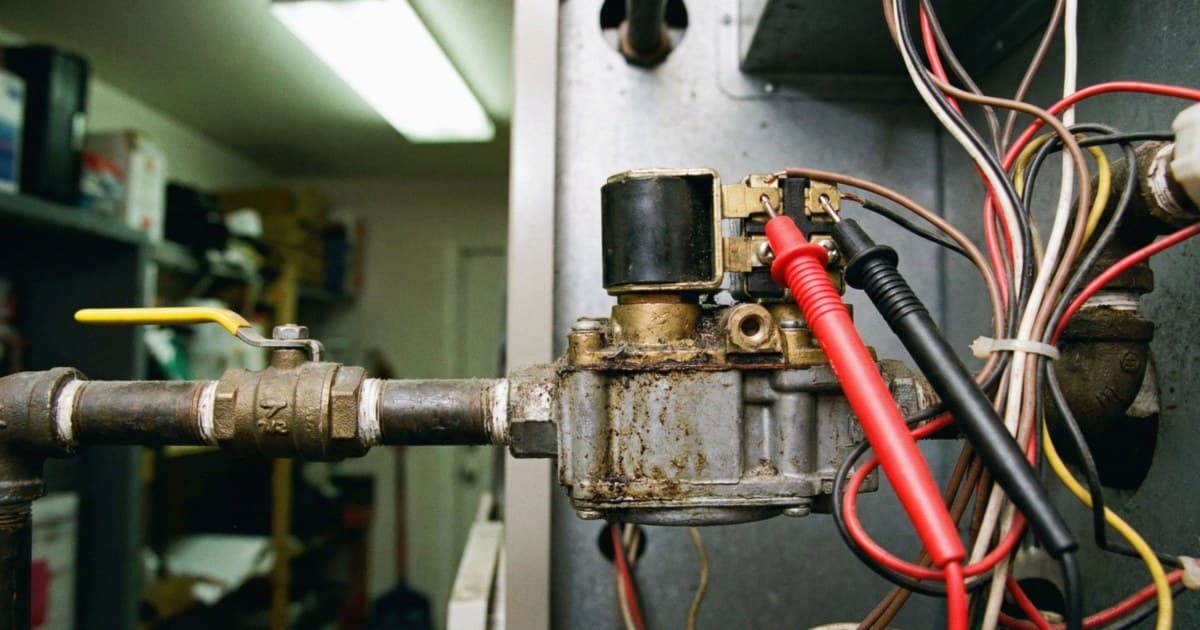
Gas Valve Testing: Solenoid and Electrical
All modern residential gas valves are solenoid-operated. The control system (furnace control board, oven controller, dryer control board) sends a voltage signal to one or more solenoid coils on the valve, which opens the valve and allows gas flow.
Solenoid Resistance Test
Set your meter to ohms (Ω).
Disconnect the solenoid wires from the control circuit harness. Touch the meter probes to the solenoid terminals.
- 40-100 ohms: Normal solenoid coil resistance for most residential gas valves
- Open (OL): Burned-out coil. Replace the valve (or the coil pack on dryers — see below)
- 0 ohms (shorted): Internal short. Replace the valve
Specific resistance values by application:
- Furnace gas valves (Honeywell VR8, White-Rodgers 36E): Approximately 40-70 ohms for the main operator solenoid
- Water heater gas valves (Robert Shaw/Invensys): 40-80 ohms
- Dryer gas valve solenoids (Whirlpool 279834 coil set): This kit contains two coils. The 3-terminal booster/holding coil reads roughly 1,300-1,400 ohms across the booster winding (pins 1-2) and roughly 500-600 ohms across the holding winding (pins 1-3). The separate 2-terminal secondary coil reads roughly 1,000-1,300 ohms. These dryer-coil values run much higher than furnace operator coils, which surprises techs used to furnace valve testing.
- Oven gas valves: Approximately 50-150 ohms depending on valve design
Voltage Test During Call-for-Heat
A solenoid that tests good at room temperature may still fail under thermal stress. The next test is to verify the control system is actually sending voltage to the valve during a call-for-heat.
Furnace: Set the thermostat to heating mode and above current room temperature. At the gas valve terminal block, measure AC voltage between the W (heat call) terminal and the C (common) terminal. You should see 24-28V AC when the board calls for gas. If voltage is present and the solenoid tested good but no gas flows, the valve body itself is seized.
Dryer: Run the diagnostic mode or start a heat cycle. Measure AC voltage at the solenoid coil terminals during the heat call phase. Should show 120V AC. No voltage = control board or wiring issue. Voltage + good solenoid + no gas = stuck valve.
Oven: Similar approach — enter a bake cycle and measure at the valve terminals. Values depend on the oven design (some use 120V, some use 24V through an igniter circuit).
Gas Valve Diagnosis by Appliance
Furnace Gas Valves
Residential furnace gas valves are combination valves — they contain a pressure regulator, the main operator solenoid, a pilot solenoid (on standing pilot systems), and sometimes a redundant safety shutoff. Common brands: Honeywell (now Resideo) VR8 series, Emerson/White-Rodgers 36E series.
Furnace no-heat, valve fault sequence:
- Verify 24V at the W terminal of the valve during a call-for-heat
- Check both solenoid circuits (main operator and pilot if applicable)
- Listen for the valve click when energized — most combo valves make an audible click when the solenoid opens
- If click is present but no gas flows through the valve: pressure regulator failure or blocked inlet
- Measure gas pressure at the valve inlet (incoming line pressure) and outlet (manifold pressure). Normal inlet: 7" W.C. natural gas. Normal outlet: 3.5" W.C. natural gas. A pressure differential that's off-range indicates a regulator problem.
Gas manifold pressure testing requires a manometer (magnehelic or U-tube). This is not optional guesswork — over-pressure burns out heat exchangers and igniters prematurely. Under-pressure causes ignition problems and incomplete combustion.
Dryer Gas Valves
Dryer gas valves differ from furnace valves in important ways:
- They operate at 120V AC (not the 24V AC used by furnace and most appliance gas valves)
- The coil set is split between a 3-terminal booster/holding coil and a separate 2-terminal secondary coil; the secondary coil energizes only after the igniter's current draw has signaled the circuit
- The coils are field-replaceable on most models (unlike furnace valves, which are replace-the-whole-valve)
The Whirlpool 279834 coil kit replaces the most common dryer valve coil set across Whirlpool, Maytag, KitchenAid, Amana, and Roper gas dryers. For more details on the full dryer gas system diagnostic, see our dryer not heating guide.
Dryer valve body failure (rare): If the coils test good, the igniter current is adequate (above 3A), and 120V is present at the valve during the heat call, but gas still doesn't flow — the valve body is stuck. This is the rare scenario where the valve body itself (not just the coils) requires replacement. Part: 279834 is coils only. For the full valve assembly: it's model-specific. Most are available at appliance parts distributors.
Oven Gas Valves
Gas oven burner valves typically come in two configurations: safety valve + spark ignition, or bimetal safety valve + standing pilot (older designs).
Safety valve + spark ignition (most post-1990 ovens): The safety valve is opened by a temperature-sensing element (capillary tube with bulb at the burner). The spark igniter lights the burner, and once the burner warms the sensing bulb, the safety valve opens fully. Problems:
- If the igniter sparks but gas doesn't light: check the safety valve and its sensing element
- If gas lights but the main burner shuts off quickly: sensing element isn't getting hot enough (dirty burner, misrouted capillary)
Testing the oven safety valve: These are typically tested by measuring the valve resistance (should be approximately 50-200 ohms depending on model) and by checking whether the sensing bulb opens the valve when heated with a heat gun during a bench test.
Oven valve replacement is a larger job than dryer valve replacement — the valve is often in a confined space, connected to both the burner and the broiler burner in many designs. Budget accordingly. For diagnostic context on oven heating problems, see our oven not heating guide.
Water Heater Gas Valves (Thermostat/Valve Combo)
Water heater gas controls are combination thermostat-valve units — the thermostat dial, the safety shutoff, the pilot valve, and the main burner valve are all in one assembly. Common brands: Robert Shaw (now Invensys/Watts), Honeywell.
Failure modes:
- Thermocouple seat/valve safety failure: Pilot lights but won't stay lit when you release the pilot button. Thermocouple millivolt output is low (test at the TC terminal — see our millivolt testing coverage in the advanced multimeter guide). Replace the thermocouple first. If the valve still won't hold after a good thermocouple: the valve's safety seat is failed. Replace the whole combo valve.
- Main valve failure: Pilot stays lit but main burner won't come on when thermostat calls for heat. Main operator solenoid or valve body. Replace the combo unit.
Replacing a water heater combo valve: shut off gas, drain down the heater to below the valve level, disconnect pilot tube and main burner tube, thermocouple, and manifold bracket. The new valve must match the pilot tube length and fitting positions exactly — this is manufacturer-specific. Buy the matching part.
When to Condemn Instead of Repair
Gas valve condemnation (full replacement, not repair attempt) is the correct call in these situations:
-
Any confirmed gas leak at the valve body — not at a fitting, but through the valve body itself. No field repair. Replace.
-
Flooding or submersion — A gas valve that has been submerged (even briefly) must be replaced. Water intrusion into the solenoid or regulator assembly causes hidden failure modes that may not appear immediately.
-
Apparent age exceeding 20 years with any degradation signs — Rubber diaphragms in pressure regulators age and crack. A 25-year-old gas valve on a furnace that's had several repairs should be replaced when you're in there anyway.
-
Manufacturer recall or service bulletin — Check the CPSC recall database and the manufacturer's service bulletin database before working on any gas valve. Several gas valve models have active recalls. Installing a recalled part (or reinstalling a recalled valve) creates significant liability.
-
Valve body has been dropped, impacted, or shows physical damage — Internal misalignment from physical damage is invisible and potentially dangerous.
What is NOT a reason to condemn: A failed solenoid coil on a dryer valve (replace the coils, not the whole valve). A failed thermocouple on a water heater (replace the thermocouple, not the valve, unless the valve seat also fails to hold after good thermocouple installation).
NFPA Codes and California Regulatory Context
NFPA 54 (National Fuel Gas Code) is the primary model standard governing gas appliance installation and repair across most U.S. jurisdictions. Note, however, that California does not adopt NFPA 54. California regulates fuel gas through its own Title 24 standards — the California Mechanical Code (Title 24, Part 4) and the California Plumbing Code (Title 24, Part 5), both based on the IAPMO Uniform Codes (the Uniform Mechanical Code and Uniform Plumbing Code) rather than the NFPA model. The Uniform Codes carry the fuel gas and venting provisions that apply in California, and specific NFPA 54 figures and standards may be referenced within them. If you work outside California, confirm which code your jurisdiction has adopted before relying on NFPA 54 directly.
Key provisions relevant to appliance service (consistent across the Uniform Codes and NFPA 54):
- All gas appliances must be listed and installed per their listing
- Gas connectors must be accessible and not run through walls, floors, or ceilings
- Appliance shutoff valves must be accessible (within 6 feet of the appliance, in the same room)
- After service, the technician is responsible for verifying a gas-tight system
California Contractor Licensing: Working on gas systems is regulated. HVAC and appliance repair contractors who work on gas appliances should carry the appropriate C-20 (HVAC) or potentially C-36 (Plumbing) license, or work under a licensed contractor. The Contractors State License Board (CSLB) takes unlicensed gas work seriously.
Documentation and liability: Document every gas call thoroughly. If you find a pre-existing unsafe condition (no accessible shutoff, flexible connector running through a wall, inadequate clearance), document it in your service report AND advise the customer in writing. Your written notice of an observed hazard that you did not create shifts the liability for that pre-existing condition.
A gas call properly documented, safely executed, and leak-checked on completion is defensible. An undocumented call where you "think" it was fine is not.
Sources
- National Fire Protection Association. NFPA 54: National Fuel Gas Code (2024). nfpa.org
- California Building Standards Commission / IAPMO. 2025 California Mechanical Code (Title 24, Part 4) and California Plumbing Code (Title 24, Part 5). epubs.iapmo.org
- Contractors State License Board (CSLB), State of California. License classifications (C-20 HVAC, C-36 Plumbing) and enforcement. cslb.ca.gov
- U.S. Consumer Product Safety Commission. Recalls database. cpsc.gov/Recalls
How do you test a gas valve solenoid?▾
Disconnect the solenoid wires and test resistance across the terminals with a multimeter. Most gas valve solenoids read 40-100 ohms. An open reading means the coil is burned out. Also verify voltage at the solenoid terminals during a call-for-heat cycle — furnace valves use 24V AC, dryer valves use 120V AC. Voltage present with a good solenoid resistance but no gas flow indicates a seized valve body, not an electrical problem.
When should I condemn a gas valve instead of repairing it?▾
Condemn and replace a gas valve when: the valve body leaks gas (not just at a fitting), the unit has been submerged in water, the valve is more than 20 years old with visible degradation, the manufacturer has a recall or service bulletin for that valve model, or the valve body shows physical damage from impact. Gas valve components are not field-serviceable on residential appliances — it's replace, not repair.
What do I do if I smell gas at an appliance?▾
Do not operate any electrical switches, ignition sources, or open flames. Shut off the gas supply at the appliance shutoff valve immediately. If the odor is strong or the shutoff is inaccessible, evacuate the building and call the gas utility from outside — do not re-enter until cleared. For service technicians, document the finding, advise the customer in writing, and do not restore gas service until the leak source is identified and corrected.
Need a repair professional?
Get free quotes from verified technicians in your area.
Find a Pro Near You